连接 Grbl
This wiki is intended to provide various instructions on how to connect to grbl in various ways. Please feel free to contribute more up-to-date or alternative methods.
这个维基旨在提供如何以不同的方式连接 Grbl 的各种说明。请随时提供更多最新的或替代的方法。
Grbl 的针脚
Pin diagram for Grbl v0.8 and v0.9 with the traditional layout: (NOTE: The probe A5 pin is only available in Grbl v0.9.)
Grbl V0.8 和 V0.9 与传统的布局引脚图(注:探头 A5 引脚仅在 Grbl v0.9 提供。)
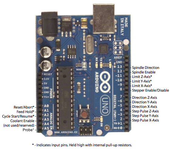
For Grbl v0.9 with variable spindle PWM ENABLED: (NOTE: The Z-limit and the spindle enable pin are swapped, because we had to access the hardware PWM on D11 for variable spindle PWM output to work.) We are still updating this pin configuration at the moment by weighing future options. We’d like to only change the pins once. Stay tuned!

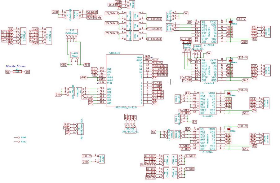
First, to connect your stepper motors to Grbl, you’ll need some stepper motor drivers to power the steppers and connect your driver inputs to the Arduino controller pins. There are a number of drivers that can do this, available as fully pre-built, partially pre-built, or completely DIY. There are some examples farther down the page. The stepper drivers will need to share the stepper enable pin (D8) to their respective enable pins, while the direction and step pulse pins (D2-D7) will need to be connected to their respective pins on the drivers. Just make sure that all of your drivers and the Arduino share a common ground (star grounded with your motor driver power). This is about all you’ll need to get started.
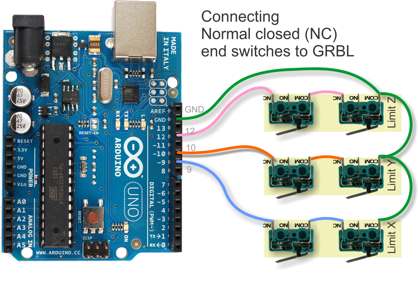
Afterwards, once you decide that you’re ready or would like to enable homing and/or hard limits, you’ll need to connect a normally-open limit switch to each of the limit pins (D9-D11). Homing and hard limits use the same switches. These limit pins are already held high with an internal pull-up resistor, so all you have to do is wire them to ground. So when you close a switch, the switch will pull the limit pin to ground. If you’d like to have hard limit switches on both ends of travel of an axis, just wire two limit switches in parallel to the axis limit pin and ground. Make sure you have the switches installed before attempting to perform a homing cycle, and make sure you practice good wiring methods to minimize external electric noise on the input pins.
之后,一旦你决定,你准备好了,或者要启用归位和/或硬限制,你需要连接一个常开限位开关到每个限位销(D9-D11)。归巢和硬限制使用相同的开关。这些限制引脚已经高举带有内部上拉电阻,所以你要做的就是把他们接地。所以,当你关闭开关,该开关将拉的限位引脚接地。如果你想在轴的行程两端都添加硬限位开关,只需将两个限位开关并联连接到该轴的限位引脚并接地。在试图执行一个归航周期之前请确保您已经安装了开关,并确保你养成良好的布线方式,以尽量减少输入引脚上的外部电噪声。
In Grbl v0.8 and later, there are pin-outs of the cycle start, feed hold, and reset runtime commands, so you can have physical control buttons are your machine. Just like the limit pins, these pins are held high with an internal pull-up resistor, so all you have to do is connect a normally-open switch to each pin and to ground. Again make sure you practice good wiring methods to minimize external electric noise on the input pins.
在 Grbl V0.8 及更高版本,有循环启动的引脚,进给保持,和复位运行命令,这样你可以为你的机器添加物理控制按键。就像限位引脚,这些引脚具有内部上拉电阻高高举起,因此,你所要做的就是将一个常开开关连接到每个引脚并接地。再次确保你已养成良好的布线方式,以尽量减少输入引脚上的外部电噪声。
If you have a desire or need for spindle or coolant control, Grbl will toggle these output pins (D12, D13, A3) high or low, depending on the G-code commands you send to Grbl. With v0.9 and variable spindle PWM enabled, the D11 pin will output a range of voltages from 0V to 5V depending the spindle speed G-code command. 0V indicates spindle off in this case. Since these pins are all application dependent in how they are used, we’ll leave it to you to determine how to control and use these for your machine. You can also hack the spindle and coolant control source files to easily alter how they work and then compile and upload your modified Grbl through the Arduino IDE.
如果你需要主轴或冷却液控制的要求,Grbl 将切换这些输出引脚(D12,D13,A3)的高低状态,根据 G 代码指令发送到 Grbl。随着 V0.9 版本可变速主轴 PWM 的启用,根据主轴转速G代码指令 D11 引脚将输出从 0V 到 5V 的电压范围。在这种情况下 0V 表示主轴关闭。以后这些引脚,如何使用它们都取决于所有应用程序,如何使用这些控制你的机器由你决定。