USB引脚
Universal Serial Bus
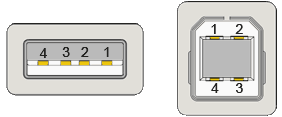
USB 1.x/2.0 Standard A/B plug (male)

USB 1.x/2.0 Mini A/B plug (male)
| Pin | Name | Description | Color | |
|---|---|---|---|---|
| Stand. | Mini/Micro | |||
| 1 | 1 | VCC | +5 V | Red |
| 2 | 2 | D- | Data - | White |
| 3 | 3 | D+ | Data + | Green |
| - | 4 | ID | OTG Identification: • host: connected to ground • slave: not connected | Not connected |
| 4 | 5 | GND | Ground | Black |
| Shell | Shield | Metal shell | Drain Wire | |
USB 3.x
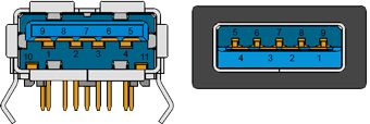
USB 3.x Standard-A Receptable (female) and plug (male)
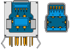
USB 3.x Powered-B Receptable (female) and plug (male)
| Pin | Signal | Description | Color (type A) | ||
|---|---|---|---|---|---|
| Type A | Type B (*) | Micro B | |||
| 1 | 1 | 1 | VBUS | Power | Red |
| 2 | 2 | 2 | Data - | USB 2.0 data | White |
| 3 | 3 | 3 | Data + | Green | |
| 4 | 4 | 5 | GND | Ground for power | Black |
| 5 | 8 | 9 | SSRX- | SuperSpeed receiver | Blue |
| 6 | 9 | 10 | SSRX+ | Yellow | |
| 7 | 7 | 8 | GND DRAIN | Ground for signal | |
| 8 | 5 | 6 | SSTX- | SuperSpeed transmitter | Purple |
| 9 | 6 | 7 | SSTX+ | Orange | |
| 10 | 10 | - | DPWR (*) PD DETECT 1 | Power provided by device /PD detect | |
| 11 | 11 | - | DGND (*) PD DETECT 2 | Ground for DPWR /PD detect | |
| - | - | 4 | ID | OTG Identification | |
| Shell | Shield | Connector metal shell | |||
(*) Powered-B USB connector allows USB accessories to draw power from peripheral devices. It is deprecated in USB 3.1 and replaced by Power Delivery (PD) specs.
Pins 10-11 are used in PD receptacle to detect a PD plug.
Standard connectors don't have the pins 10-11.
USB 3.1 Type-C
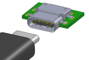
USB Type-C Receptacle Interface (Front View)
| A1 | A2 | A3 | A4 | A5 | A6 | A7 | A8 | A9 | A10 | A11 | A12 |
| GND | TX1+ | TX1- | Vbus | CC1 | D+ | D- | SBU1 | Vbus | RX2- | RX2+ | GND |
| GND | RX1+ | RX1- | Vbus | SBU2 | D- | D+ | CC2 | Vbus | TX2- | TX2+ | GND |
| B12 | B11 | B10 | B9 | B8 | B7 | B6 | B5 | B4 | B3 | B2 | B1 |
USB Type-C Plug Interface (Front View)
| A12 | A11 | A10 | A9 | A8 | A7 | A6 | A5 | A4 | A3 | A2 | GND |
| GND | RX2+ | RX2- | Vbus | SBU1 | D- | D+ | CC | Vbus | TX1- | TX1+ | GND |
| GND | TX2+ | TX2- | Vbus | Vconn | SBU2 | Vbus | RX1- | RX1+ | GND | ||
| B1 | B2 | B3 | B4 | B5 | B6 | B7 | B8 | B9 | B10 | B11 | B12 |
Connector includes both USB 2.0 (D+ and D鈭�) and USB 3.1 (TX and RX pairs) data buses, USB power (VBUS) and ground (GND), Configuration Channel signals (CC1 and CC2), and two Sideband Use (SBU) signal pins.
Not all signals are required in all platforms or devices.
USB Specifications
- USB Power Specification- USB Power Delivery Specification
- USB Speed Specification


 支付宝打赏
支付宝打赏  微信打赏
微信打赏 


